RYA Day Skipper standard — precise, complete
A marine diesel engine will only run correctly if it receives clean air in sufficient quantity and can expel exhaust gases safely. Air supply and exhaust are therefore treated together by the RYA as one functional system.
1) Purpose of the Air System (RYA concept)
The air system must:
Supply clean air for combustion
Allow complete exhaust gas removal
Prevent water entering the engine
Control engine room temperature and pressure
Restricted airflow causes power loss, smoke, overheating, and eventual engine damage.
2) Air Intake System (Combustion Air)
2.1 Air inlet
Engine draws air from the engine space or via a dedicated intake duct.
Intake must not be blocked or restricted.
Engine space must be ventilated to prevent oxygen starvation.
2.2 Air filter
Removes dust and particles before air enters cylinders.
Can be:( dry paper element or oil-bath type in older engines)
Blocked filter results in (loss of power, black smoke, increased fuel consumption)
2.3 Induction manifold
- Distributes air evenly to each cylinder.
- Leaks reduce efficiency and cause uneven running.
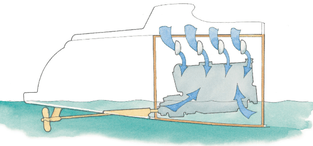
3) Engine Space Ventilation
3.1 Ventilation ducts
Allow cool air in and hot air out of the engine compartment.
Prevent overheating of (engine, alternator, electrical components)
3.2 Forced ventilation (if fitted)
Blowers sometimes fitted, especially on petrol engines.
Diesels normally rely on natural ventilation but may have fans.
RYA principle:
An engine cannot breathe if the engine space cannot breathe.
4) Exhaust System (Air Out)
4.1 Exhaust manifold
Collects exhaust gases from each cylinder.
Often water-cooled to reduce temperature.
4.2 Mixing elbow (water injection point)
Cooling water injected into exhaust gases.
Lowers exhaust temperature.
Prevents damage to hoses and fittings.
Common failure point due to corrosion and carbon build-up.
4.3 Exhaust hose
Carries water-cooled exhaust gases aft.
Must be: (heat resistant, properly supported, free of cracks and soft spots)
4.4 Waterlock (exhaust silencer)
Collects water from exhaust system.
Prevents water flowing back into engine when stopped.
Also reduces noise.
4.5 Anti-siphon loop (if fitted)
Prevents seawater siphoning back into engine when stopped.
Must rise above waterline.
Vent must be clear.
4.6 Exhaust outlet
Final discharge point overboard.
Visual confirmation of: (exhaust gases, cooling water flow)
5) Critical Risks (RYA emphasis)
5.1 Water ingress via exhaust
Water can enter cylinders if:
Excessive cranking floods waterlock
Engine stopped abruptly while heeled
Anti-siphon valve fails or blocks
Consequence: hydraulic lock → bent conrods → engine failure.
5.2 Restricted air supply
Causes:
Blocked air filter
Poor engine room ventilation
Obstructed intake ducts
Symptoms:
Black smoke
Loss of power
Rough running
5.3 Exhaust blockage
Causes:
Collapsed exhaust hose
Carbon blockage in mixing elbow
Obstruction at outlet
Symptoms:
Overheating
Loss of power
Excessive smoke
6) Day Skipper Checks (Pre-start & Running)
Before start:
Engine space ventilated
Air filter visually clean
Ventilation openings clear
After start:
Exhaust outlet discharging water and gases
No exhaust leaks
No excessive smoke
Underway:
Monitor smoke colour
Listen for exhaust note change
Smell for exhaust leaks
7) Smoke Colour Reference (RYA practical guide)
Black smoke → too much fuel or not enough air
White smoke → unburnt fuel (cold engine, injector issues)
Blue smoke → oil burning
Air system problems most commonly produce black smoke.
8) Revision Summary (Speakable)
Air in through ventilated engine space → air filter → inlet manifold → cylinders.
Exhaust out through manifold → mixing elbow → hose → waterlock → outlet.
If air cannot get in or exhaust cannot get out, power drops, smoke increases, and damage follows.